At ground level, the wall, floor, external surface and any underfloor void meet. Understanding that junction helps explain why floor construction, external levels, ventilation and water routes belong in the same investigation.
Compare solid and suspended floors, locate openings and trace the relationship between inside and outside. The examples concern existing British buildings; basement waterproofing and flood design need separate guidance.
Read the junction in section
Picture a line from the external ground, through the wall base and into the room. Along that line, identify the outside surface level, the internal floor, any known damp-proofing and any void below the floor. The floor comparison and source guidance below explain why these relationships matter.
A suspended floor introduces a void and a ventilation question. A solid floor raises a different set of questions about its layers and connection to the wall. Establish which arrangement is present before using an airbrick or a wall-base mark to explain the whole junction.
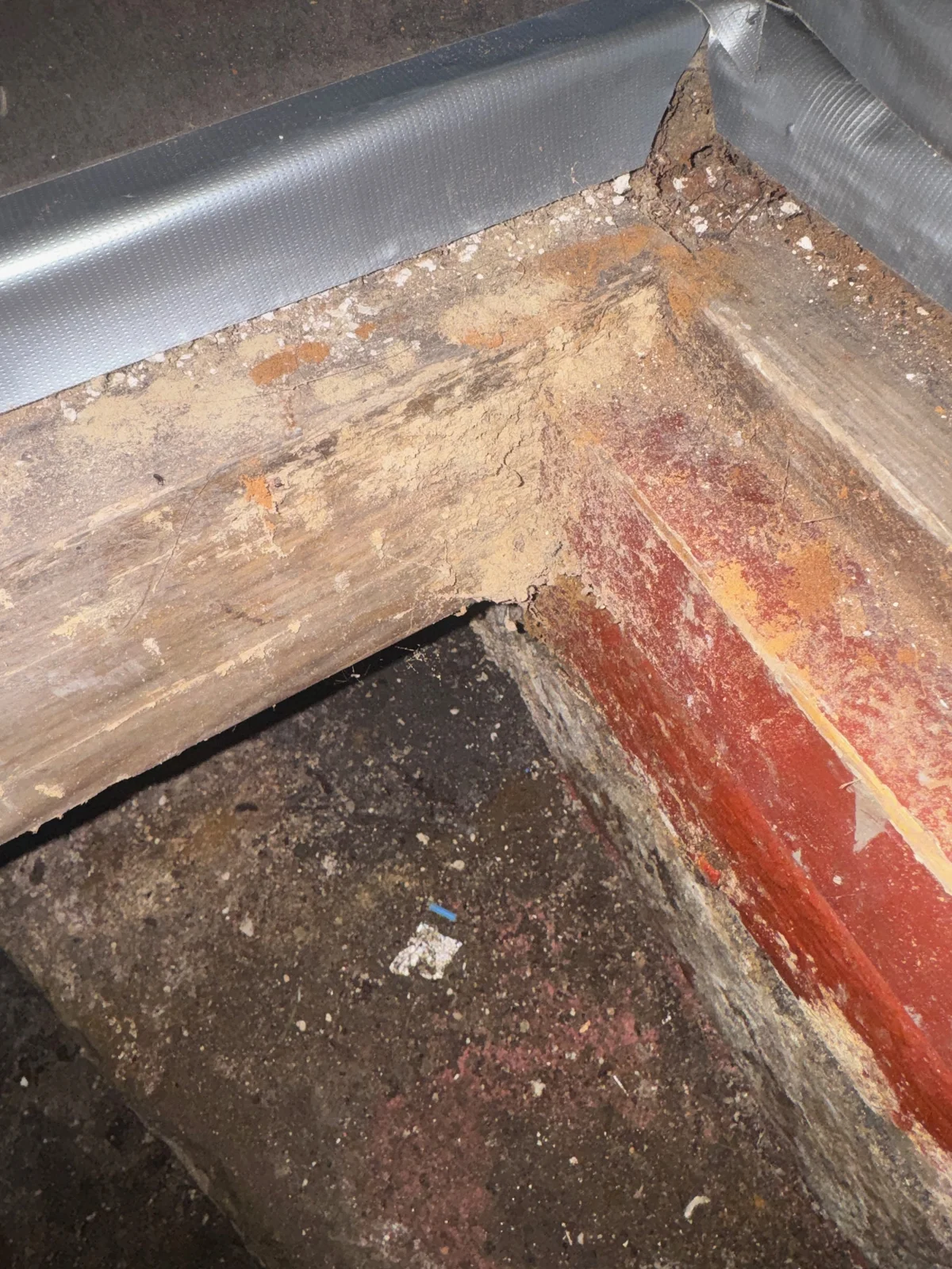
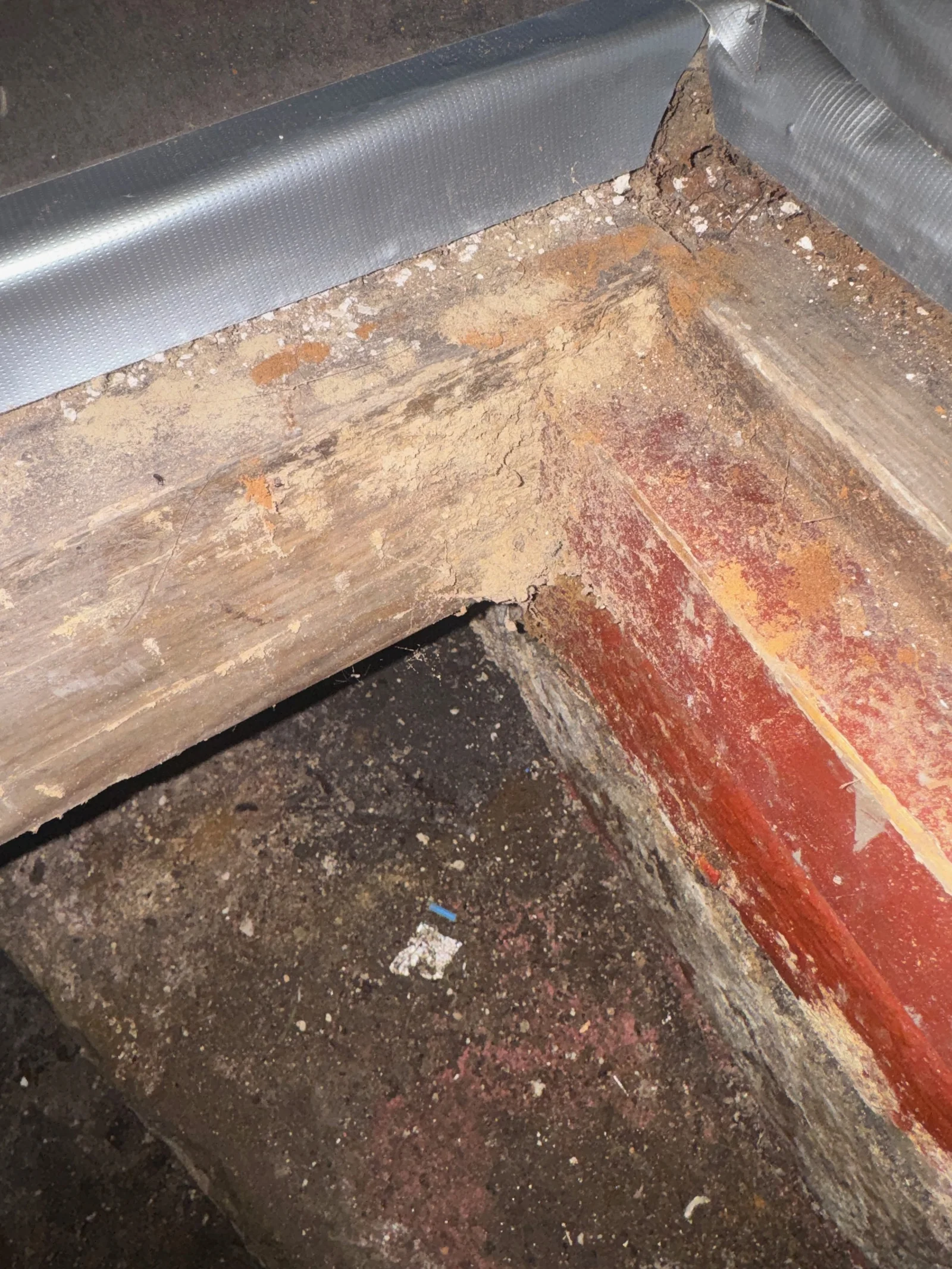
The hatch edge exposes a small part of the floor opening and its timber frame. The view records that junction; it does not show the full floor arrangement, the supports beyond it or whether entry is safe.
Survey archive photograph · View larger image
First, identify the floor
Before interpreting a damp wall base, establish what the wall is meeting. The following illustration compares two floor arrangements; it is a starting vocabulary, not a complete catalogue.
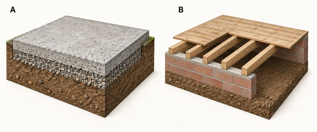
Illustration notes
AI-generated illustration.
In the suspended example, separate the boards, joists, bearing supports, void and ground beneath. Historic England describes this construction and the roles of separation from ground moisture and subfloor ventilation. A thin concrete covering beneath an old timber floor is not, by itself, evidence of an effective moisture barrier. See HEAG086, sections 1.1 and 1.4, printed pages 3 and 5. Its publisher currently marks the guidance as under review; the construction description is used here, not its retrofit details as a current design specification. Historic England: suspended timber floors.
Concrete floors can also be suspended; Approved Document C treats them separately from ground-supported floors. A hard surface alone therefore does not identify the support arrangement. Approved Document C, section 4.
On an inspection sketch, label each construction statement seen, documented or unconfirmed. “Timber finish seen” and “suspended timber structure confirmed” are different records. Mixed or altered floors need separate locations.
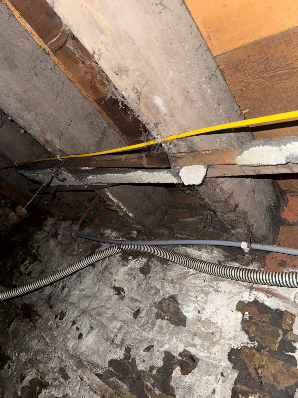
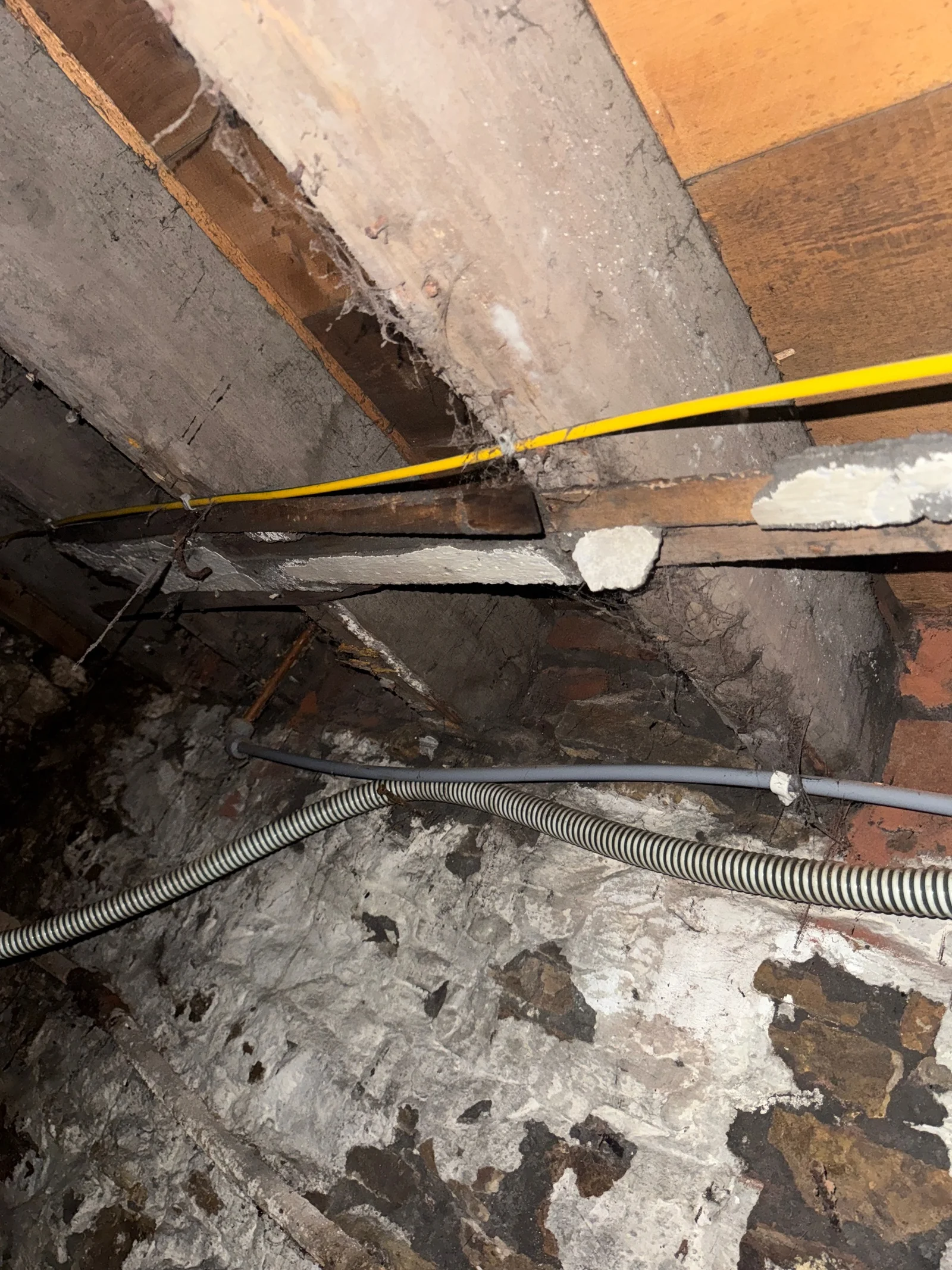
Seen from the cellar, timber joists and the underside of boards locate the supporting structure beneath the floor finish. Services cross the view. Concealed bearings, member dimensions and the condition of the whole floor remain separate questions.
Survey archive photograph · View larger image
Keep the junction's parts distinct
Use these questions when reading a drawing or describing what is accessible. They organise the investigation; they do not establish concealed details.
| Part | Question to resolve | Evidence to keep |
|---|---|---|
| Wall damp-proof course (DPC) | What supports identification of this particular course? | Location, material if established, photographs and extent visible |
| Floor damp-proof membrane (DPM) | Is a membrane actually evidenced, and is its wall connection known? | Accessible detail or reliable drawing; mark concealed continuity unconfirmed |
| External ground or paving | How does the surface relate to the wall, vent and internal floor here? | A located section, named measurement endpoints and units |
| Subfloor opening and void | Where does this opening lead, and which parts of the route can be checked? | Exterior view plus separately identified internal observations |
| Surface-water route or drain | Where does water arrive, collect and leave? | Conditions during inspection, observed route and outfall evidence |
What the 150 mm reference actually says
England's Approved Document C, paragraph 5.5, gives a technical solution with an external DPC at least 150 mm above adjoining ground, unless part of the building's design protects the wall. It also calls for continuity with any floor DPM. That solution excludes groundwater pressure. Approved Documents provide compliance guidance and allow other solutions; this dimension alone is not a diagnosis or a retrospective compliance assessment. Use of guidance, printed page 3; paragraph 5.5, page 29.
The practical consequence is to name the endpoints before quoting a clearance. “Paving to visible slate course” records something different from “paving to assumed DPC”. If the identification is uncertain, keep that uncertainty attached to the number. Check the relevant country, date, work and detail before making a regulatory statement.
Consider more than one water route
Raised external levels can allow lateral moisture penetration. Historic England also identifies drainage faults, supply leaks, splashback and condensation as possible explanations for dampness at a wall base. Map external levels against the internal affected area before deciding what requires investigation. Assessing Damp in Historic Buildings, June 2026, printed page 24.
For this library, organise each possibility as a question with a useful observation:
- External water: can the water's arrival and route be observed in suitable conditions?
- A buried service or drain: what targeted inspection would distinguish a defect from an assumption?
- Internal conditions: what time, location and environmental evidence would help test the explanation?
- An alteration: is there reliable evidence of what changed, where and when?
Several routes may need consideration; proximity alone does not establish causation. Use Investigating moisture for the wider evidence method and measurement limitations.
Follow the ventilation route
An airbrick is an accessible starting point. The practical question continues behind it: does it connect to the relevant void, and is the route through that void established? Approved Document C's suspended-timber solution describes opposing openings and a free path to all parts of the void. Paragraph 4.14, printed pages 26–27.
That supports a limited inference: seeing a clear outer grille does not establish the whole concealed route. Record what was accessible, the direction viewed and any areas screened from view. Do not convert an inaccessible void into either “satisfactory” or “defective” without supporting evidence. The companion field method uses a real photograph to practise that distinction.
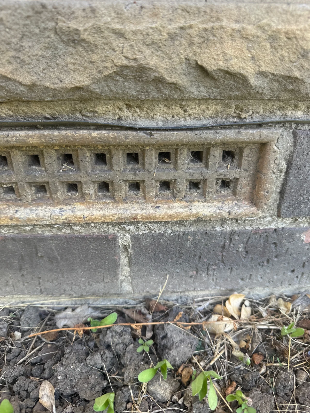
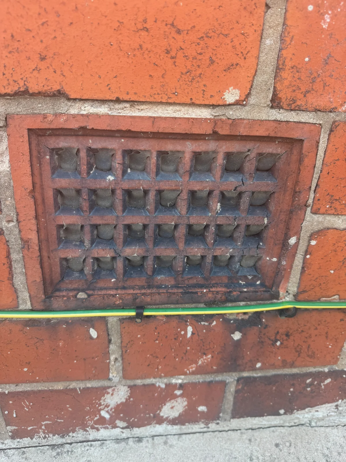
The air brick sits above the adjacent soil, with openings visible at its face. Compare the outside opening with the accessible floor construction; neither its clearance nor the complete airflow route can be measured from this photograph. This is a different property from the obstructed example below.
Survey archive photograph · View larger image
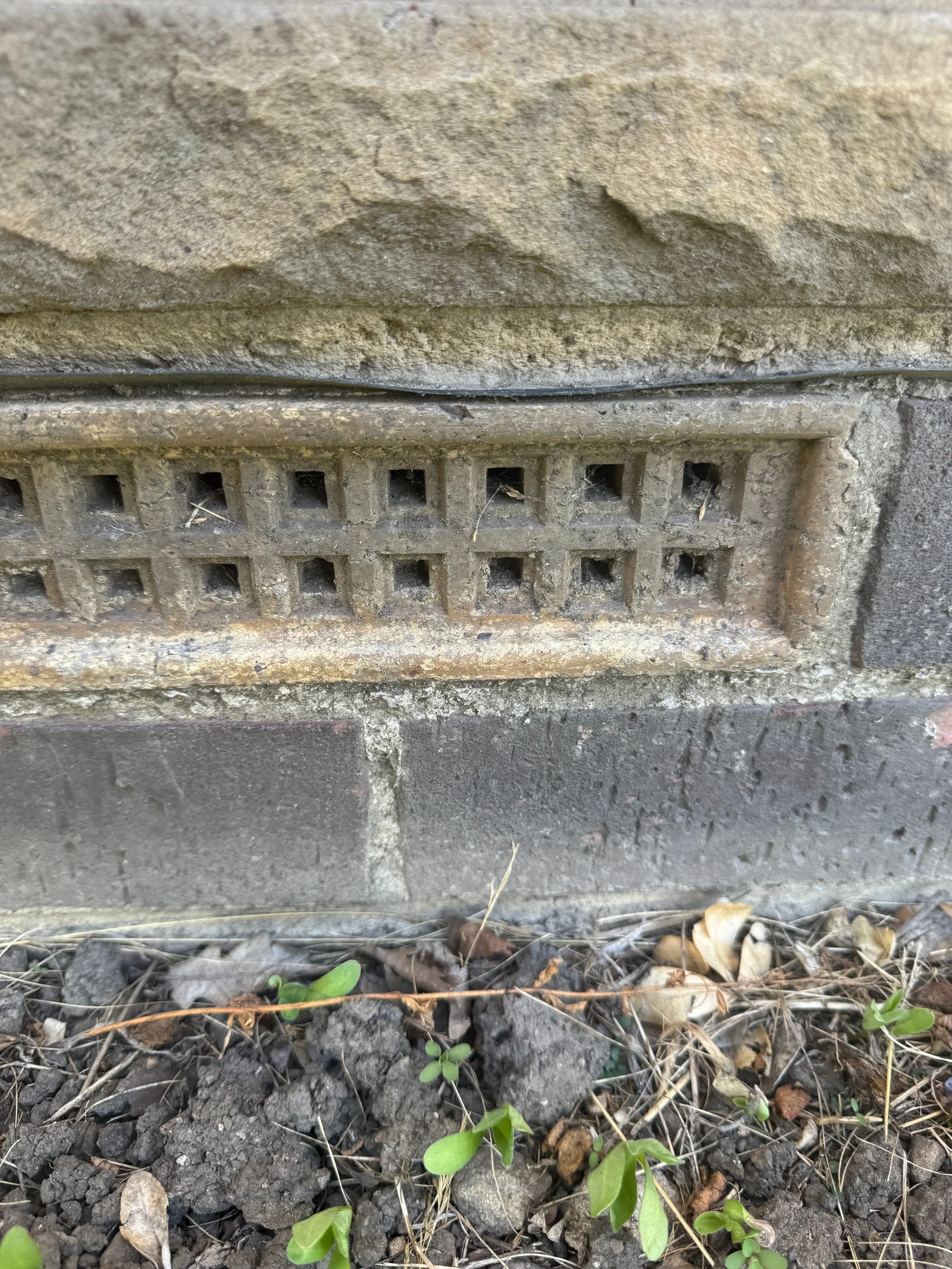
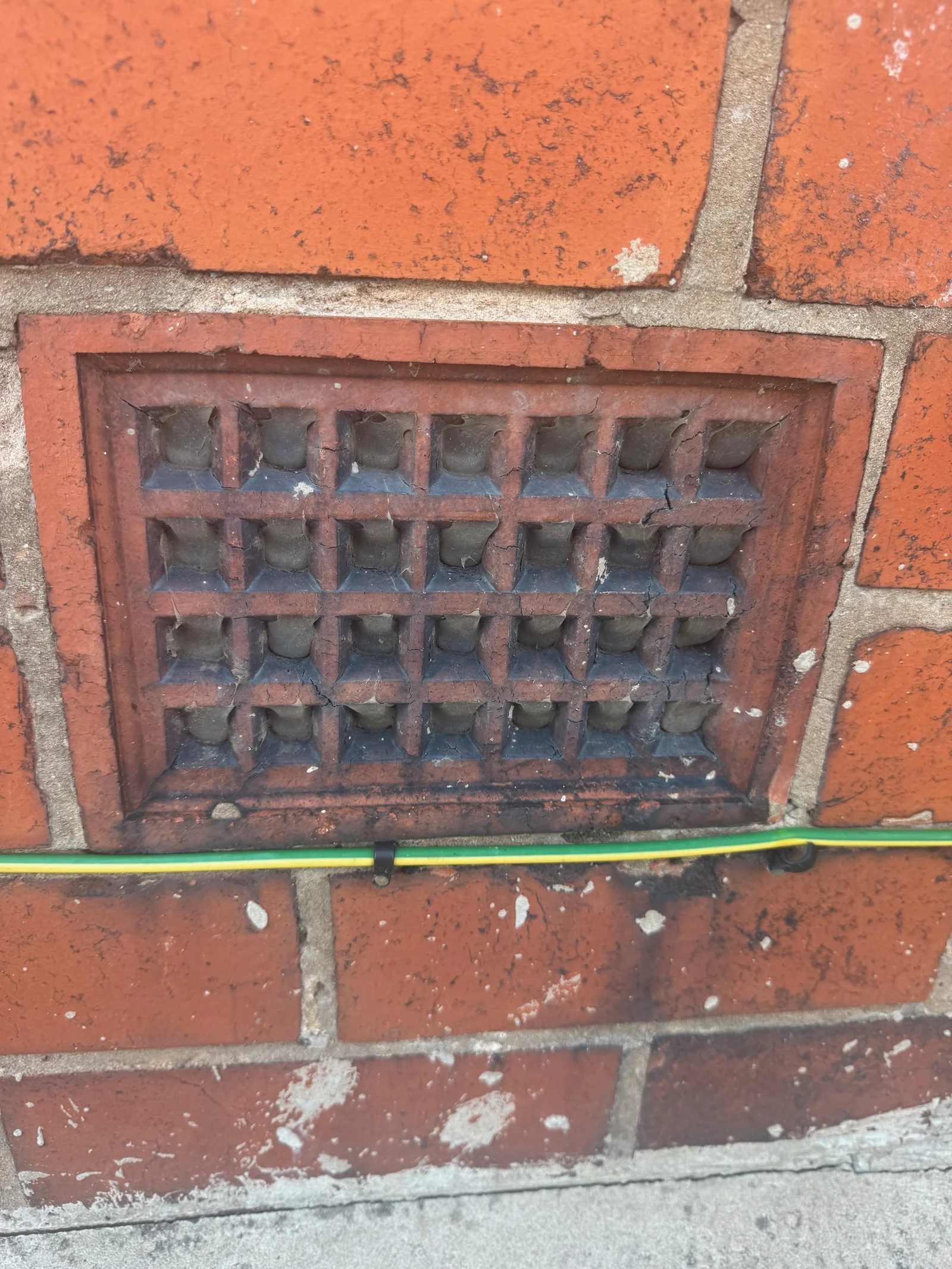
The openings in this air brick are visibly obstructed. The external face is only one part of the ventilation route: the floor construction and route behind it still need to be established.
Survey archive photograph · View larger image
A drain needs a reason and a destination
SPAB explains that French drains can help in appropriate circumstances, but can also cause problems near shallow foundations or retain water when blocked. Their suitability depends on the moisture source, a workable outlet and maintenance. A gravel strip is therefore not enough to establish that a functioning drainage system exists. SPAB: French drains.
Before proposing an intervention, write its intended result: “intercept this identified water route” is more reviewable than “install drainage for damp”. Establish what evidence supports that result, what remains concealed and who needs to design the work. This guide supplies no universal trench depth, offset or excavation detail.
Excavation must account for foundations, services and ground stability; HSE requires these risks to be addressed before the work. A survey observation is not an instruction to dig beside an unknown footing. HSE: excavations.
Turn understanding into an inspection
Take three linked questions forward: what is built here; what has actually been observed; what would change the advice? The ground and subfloor field method turns them into a located record and a short exercise. If distortion or movement is also present, retain that as a separately evidenced line of enquiry using Cracking and movement.